

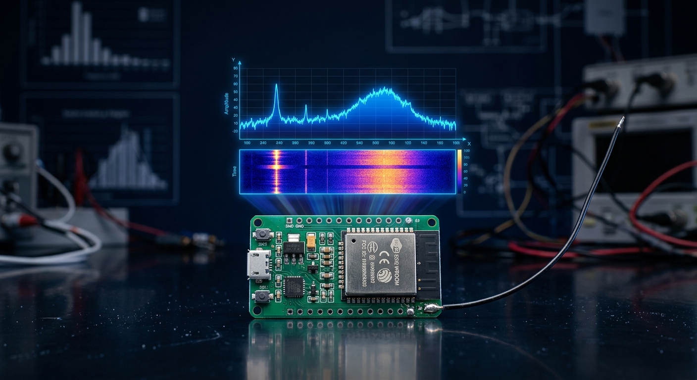
Until recently, looking at the raw radio spectrum around 2.4 GHz meant buying dedicated hardware: an RTL-SDR dongle, a HackRF, or something in the USRP price bracket. That assumption just broke. Researchers at ESPARGOS found an undocumented mode inside the ESP32 itself that lets the chip capture raw I/Q baseband samples straight from its internal modem ADC — no extra radio, no soldering, no external SDR.
In this article we look at what ESP-SDR actually is, what the silicon does differently in this mode, which chips support it, what you can genuinely receive with it, and how to try it in your browser in about five minutes with a board you may already have in a drawer.
The discovery: a debug path that was never in the datasheet
Every ESP32 contains a complete 2.4 GHz radio front-end, an ADC/DAC stage and a fixed-function Wi-Fi modem. Normally the ADC output flows straight into that modem, and the CPU only ever sees processed results — decoded packets, or for research hardware such as ESPARGOS, channel state information (CSI).
The ESPARGOS team started from the adctrig function inside Espressif’s own librftest library, reverse engineered it (with help from LLMs) and found that the modem’s sample-dump engine can be pointed at internal SRAM. Special debug registers configure the modem to write raw baseband samples directly into a memory region that the firmware has reserved so the heap cannot touch it. The result: the CPU gets access to the actual radio signal, before Wi-Fi processing touches it.
Their conclusion is that Espressif engineers most likely left the path in place for on-wafer modem testing in the fab. It is an undocumented capability — not a datasheet feature, and, as the team emphasises, not a backdoor.
How the capture works
The exact mechanism, trigger modes and memory allocation differ between chips, but the pattern is always the same. Take the ESP32-C61: its SRAM is organised into banks, and the ESP-SDR firmware uses two of them as a ring buffer. One bank is temporarily handed to the modem, which writes IQ samples into it, while the other bank belongs to the CPU, which copies completed samples out to a transfer buffer. The firmware tracks the hardware write pointer to detect when the modem has moved on to the next bank — each bank holds 64 KiB.
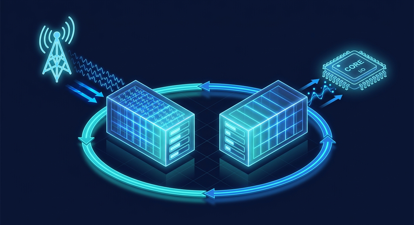
That double-buffering is what makes burst capture possible on a chip with no DMA path for this data. It is also the reason most ESP32 models can only capture in short windows rather than continuously.
What the samples look like
Each complex sample occupies one 32-bit word, and the fields are refreshingly readable:
| Bits | Field | Meaning |
|---|---|---|
| 31–28 | AGC state | Most likely the internal state of the automatic gain control FSM |
| 27–20 | RX gain | Index into the receiver gain table |
| 19–10 | I (in-phase) | Signed 10-bit, −512 to +511 |
| 9–0 | Q (quadrature) | Signed 10-bit, −512 to +511 |
Only about 20 bits of each word carry payload, but 10-bit IQ is more than enough for spectrum analysis, energy detection, direction finding and signal classification.
Capture specifications
| Parameter | Value |
|---|---|
| Tuning range | 2.2 – 2.7 GHz; 4.8 – 6.0 GHz on ESP32-C5 only (PLL stability limits differ per chip) |
| Sample rate | Up to 80 MSa/s raw complex IQ into memory, host transfer at low duty cycle |
| Analog RX bandwidth | ~13 – 54 MHz depending on chip and filter settings |
| Gain control | Internal hardware AGC or manually selected fixed receiver gain |
| Transmit | Technically possible, including phase-coherent TX on ESPARGOS One — deliberately not released |
Supported chips today: original ESP32, ESP32-C2, C3, C5, C6, C61, H2, S2, S3 and ESP32-S31. Each new chip needs its own implementation.
Beyond 2.4 GHz: catching LTE and 5G NR
Because ESP-SDR can tune past the officially supported range, the ESP32-C61 reaches up to 2.7 GHz — which includes real cellular bands such as LTE band 7 and 5G NR band n7 around 2.6 GHz. The ESPARGOS demo shows an LTE signal at 2.63 GHz sampled continuously at 40 MSa/s over Ethernet and displayed in Gqrx. This is not a lab curiosity: it means a €3 chip can observe the cellular spectrum around you.
Try it in your browser in five minutes
- Flash the firmware. Connect a supported board over USB — preferably its native/debug port — and install the SDR firmware with the ESPARGOS web flasher.
- Power-cycle. Unplug the board for five seconds, then reconnect so the new firmware boots.
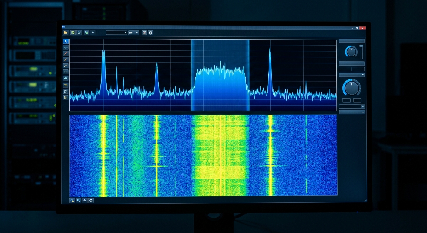
- Open ESP-WebSDR. Select your device in the browser interface and you get a live power spectrum plus a waterfall diagram of the captured IQ samples.
The browser demo runs at a deliberately low duty cycle to keep the UART link from becoming the bottleneck, but it is enough to see what is happening in the air around you — Wi-Fi traffic, Bluetooth activity, microwave oven noise and all.
The catch: getting samples off the chip is the real bottleneck
At 80 MSa/s with 32 bits per sample, the modem is writing 2,560 Mbit/s into SRAM. The output link is far slower:
| Output path | Throughput |
|---|---|
| UART (most ESP32 boards) | ~3 Mbit/s |
| SPI (ESPARGOS One internal transport) | ~13.3 Mbit/s |
| High-speed USB (ESP32-S31) | 480 Mbit/s — up to 20 MSa/s continuous |
| Gigabit Ethernet (ESP32-S31) | 1,000 Mbit/s — up to 40 MSa/s continuous |
On serial-burst profiles this means a low duty cycle and the possibility of missing packets between capture windows. Only the ESP32-S31 offers genuinely continuous IQ reception, through its native high-speed USB port or Gigabit Ethernet.
What this means for IoT and industrial engineers
- A spectrum analyzer for the price of a development board. Commissioning an industrial site? You can check 2.4 GHz congestion, BLE beacons and rogue emitters before you deploy a single sensor.
- Unencrypted ISM traffic is now visible to anyone. If your legacy sensors transmit in the clear, a €3 board can observe that. The underlying issue is the missing encryption, but it raises the bar for site security reviews.
- New options for wireless research. Raw IQ beats pre-processed CSI for anything that is not a standard Wi-Fi packet — more on that in our applications article.
Conclusion
ESP-SDR turns a commodity microcontroller into a low-cost SDR for the 2.4 GHz ISM band and a slice of the 5 GHz band. It will not replace a HackRF or a USRP — the duty cycle and the lack of a transmitter implementation are real limits — but for spectrum awareness, signal localisation and wireless research it changes the economics completely. If you have an ESP32 board and a USB cable, you are five minutes away from seeing the air around you.
📞 Contact TDLOGY today for a FREE consultation!
Planning a wireless or industrial IoT deployment and want to know what is really happening in your 2.4 GHz airspace? Our engineers can help you survey, design and deploy.
🌐 Website: tdlogy.com
📧 Email: contact@tdlogy.com
📱 Hotline: 0969.528.497
Sources: ESPARGOS — ESP-SDR: Raw IQ Capture with Espressif’s ESP32 Chips, ESPARGOS/esp-sdr on GitHub (GPL-3.0).

Leave a Reply